

























Heat Flow Meter vs 3D Thermal Properties Analyzer: Which Materials Need Each Method
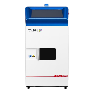
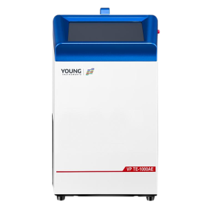
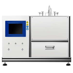
A Heat Flow Meter (HFM) measures thermal conductivity and thermal resistance under steady-state heat flow. It is commonly used for insulation and building materials such as mineral wool, foam plastics, vacuum insulation panels, gypsum board, and concrete. A 3D Thermal Properties Analyzer is designed for more complex samples, including layered and anisotropic materials, where in-plane and through-plane thermal conductivity may differ.
The choice depends on the material, specimen dimensions, test direction, and thermal properties you need to measure. This guide explains how the methods differ and what to consider when selecting an instrument.

The Main Difference: Test Setup and Heat-Flow Direction
An HFM places a specimen between two temperature-controlled plates and measures heat flow through it under steady-state conditions. The result describes thermal conductivity in the direction of heat flow through the specimen. If a material’s properties vary by direction, the specimen orientation and the direction being tested need to be specified; one HFM measurement does not describe every direction in the material.
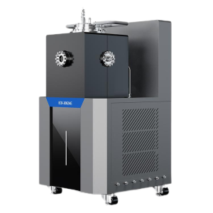
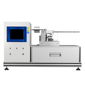
A 3D Thermal Properties Analyzer uses non-contact infrared thermography and 3D heat-transfer model inversion. The TCA 3DP-160E is designed to measure in-plane and through-plane thermal conductivity in pouch lithium-ion batteries and other suitable layered or anisotropic structures. These directional results can help characterize materials whose heat-transfer behavior depends on orientation.
The instruments are designed for different sample types and measurement questions. The distinction is not simply that one is more accurate or more advanced than the other.
When to Use a Heat Flow Meter
An HFM is a suitable choice when you need to measure the steady-state thermal conductivity or thermal resistance of insulation and building materials in a defined heat-flow direction.
Materials commonly tested with an HFM
- Fiberboard and fiber sheets
- Loose-fill glass fiber, mineral wool, and ceramic fiber
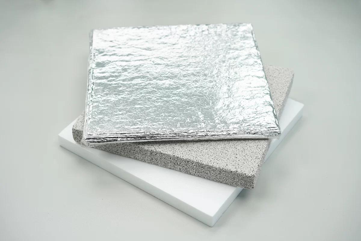
- Foam plastics, including PUR, EPS, XPS, and polyimide
- Powders, foam glass, and foam rubber
- Vacuum insulation panels (VIPs)
- Multilayer composite panels and gypsum board
- Wood, cement, sand, and soil
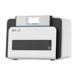
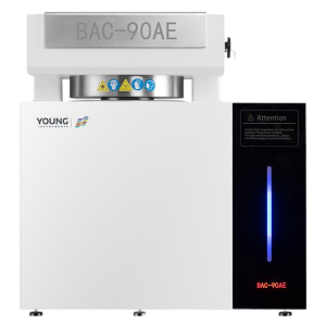
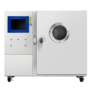
For the HFM 510AE, the listed specimen size is 300 mm × 300 mm, with a thickness range of 5–100 mm. Check the instrument’s measurement range, specimen dimensions, surface condition, and test procedure against your material before testing. For compressible specimens, the thickness used for the test may be the specified target thickness rather than the specimen’s uncompressed thickness.
The HFM 510AE Heat Flow Meter measures thermal conductivity and thermal resistance using the heat flow meter method. It is listed for testing materials including EPS, XPS, rigid PU foam, mineral wool, aerogel, foam glass, concrete, and gypsum. See the HFM 510AE Heat Flow Meter.
How the Heat Flow Meter Method Works
The specimen is placed between two plates. The instrument adjusts the plate temperatures to reach the selected mean specimen temperature and temperature difference. Heat then flows through the specimen from the warmer plate toward the cooler plate.
Two calibrated heat-flow sensors measure the heat passing through the specimen. Once the system reaches the specified thermal-balance threshold, the instrument uses the measured heat flow, temperature difference, and specimen thickness to calculate thermal resistance and thermal conductivity according to Fourier’s law. The sensor output is calibrated using reference specimens.
Thermal terms used in HFM testing
- Thermal conductivity (λ or k): Describes a material’s ability to conduct heat. It is commonly reported in watts per metre-kelvin (W/(m·K)).
- Thermal resistance (R): Describes resistance to heat flow. Area-normalized specimen thermal resistance is commonly reported in m²·K/W; total resistance for a component may be reported in K/W.
- Thermal impedance: Describes opposition to heat flow along a thermal path and the temperature rise associated with heat transfer. Units depend on the measurement convention and may include K/W or K·cm²/W.
- Thermal transmittance (U-value): The reciprocal of the total thermal resistance of a defined component or assembly. It is commonly reported in W/(m²·K); a lower U-value indicates less heat transfer through the assembly.
When to Use a 3D Thermal Properties Analyzer
Consider a 3D Thermal Properties Analyzer when the sample has a layered or anisotropic structure and the test requires thermal conductivity in more than one direction. Examples include pouch lithium-ion batteries and suitable carbon-fiber laminates or other layered composite structures.
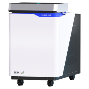
The TCA 3DP-160E uses non-contact infrared thermography and 3D heat-transfer model inversion to measure in-plane and through-plane thermal conductivity. Its product specifications list in-plane dimensions up to 400 mm × 250 mm and a through-plane dimension of 3–20 mm. Confirm that your specimen type, dimensions, and measurement objective fit the instrument’s requirements.
Learn more about the TCA 3DP-160E 3D Thermal Properties Analyzer.
How to Choose Between the Two Methods
| Consideration | Heat Flow Meter | 3D Thermal Properties Analyzer |
|---|---|---|
| Typical measurement approach | Steady-state heat flow between temperature-controlled plates | Non-contact infrared thermography and 3D heat-transfer model inversion |
| Typical sample focus | Insulation and building materials | Layered, heterogeneous, or anisotropic samples such as pouch batteries and suitable composites |
| Thermal directions | Conductivity in the direction of heat flow through the specimen | In-plane and through-plane conductivity, as supported by the test setup |
| Key practical check | Specimen size, thickness, compressibility, and test standard | Sample structure, dimensions, orientation, and suitability for the measurement model |
Questions to ask before testing
- Is the specimen an insulation or building material? An HFM may be appropriate for steady-state thermal conductivity or resistance testing.
- Do you need a result for a defined heat-flow direction? Confirm that the specimen orientation and test setup match the direction of interest.
- Is the material layered or anisotropic? If in-plane and through-plane properties are both needed, consider a 3D thermal properties analyzer designed for that sample type.
- Does the sample meet the instrument’s size and thickness requirements? Check the product specifications before preparing or cutting the specimen.
- Will the result be used for certification or customer specifications? Confirm the required test standard and protocol for the target application.


